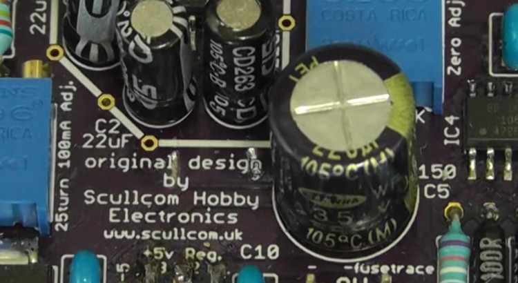
This is an update to my earlier Milliohm Meter project. Here we use a small custom PCB which is available to use. There are also some improvements to the design and the project is built in to a small case.
Below are the links to download the updated schematic, front panel artwork, drill template for case and full detailed parts list.
Below is the link for the PCB from OSH Park: https://oshpark.com/shared_projects/UWvehNO2
If of interest, in addition the Scullcom T-Shirt is a available from http://www.redbubble.com/shop/scullcom
Please note:
Save the front panel artwork and drill template pdf files to your PC hard drive and then open them up again in your PDF reader so as to ensure they are the correct size.


Are you still creating videos about projects you design and build? I haven’t seen anything new for quite some time. I like your videos and projects and would like to see more.
Hi I was wondering if you were going to try to make a spectrum analyser for upto 3GHz?
Kind Regards
there are some projects for this out on the WEB using voltage controlled varactor IC tuners salvaged from TV”s.
……
establishing the correct time base sweep voltage is the trick.
Hi Louis!
It seems that all the links to download schematics, software etcc doesn’t work anymore, system says the page doesn’t exist….there is another way to download ?
many Thanks
Hi there. I was wondering why the 100k zeroing pot
is only between ground and positive. From what I’ve seen, offset of opamps can be either positive or negative, requiering adjustment in either direction.
Thank you for your projects. I enjoy them very much