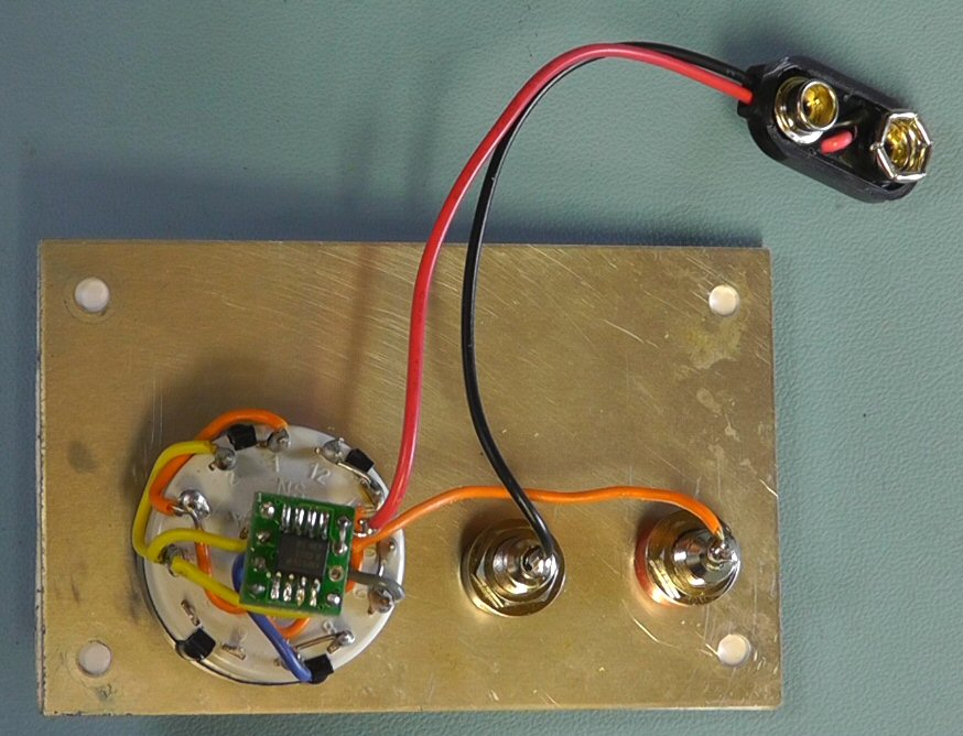
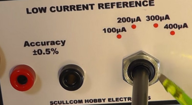
In this project we will design and built a Low Current Reference Source which has four switched ranges, namely; 100μA, 200μA, 300μA and 400μA. No calibration is required and it will operate from a standard 9 volt battery with no on/off switch. The unit will have an accuracy of ±0.5% or better.
This project uses the Texas Instruments REF200 Dual Current Source and Current Sink I.C. This I.C. can operate over a wide voltage range from 2.5 V to 40 V and still maintain the accuracy of the output current source. Accuracy of the I.C. is ±0.5%. It also has a very low temperature Coefficient: ±25 ppm/°C.
From the links below you can download the schematic, wiring diagram and front panel artwork for this project.
Low_Current_Ref_Schematic.pdf
Low_Current_Ref_Wiring.pdf
Low_Current_Ref_front_panel.pdf


I am not understanding the reason there are 3 poles on the switch. Why not just 2 poles?
100µA (1) is always connected to the output. There is no need for a switch pole for that line. 100µA (2) is connected in position 2 and 4 = 1P4T, 2 wires
200µA (3) (mirror) is connected in position 3 and 4 = 1P4T, 2 wires
what am i missing?
Dear sir,
Your circuit is useful in designing the current source.
In your REF 200 demo, what is the reason for taking the output current from Mirror common (pin 3)? But as per datasheet pin4 is mirror output. What is the reason behind connecting Mirror output (pin4) to VCC (i.e. pin 7 and 8)?
with regards,
Miss Ramya Anand,
Research scholar,
National Institute of Technology, Tiruchirappalli, India.