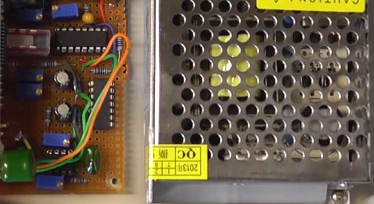
This is an update to the Function Generator project in which I discuss some modifications/enhancements following feedback from my viewers.
The latest version of the schematic which includes these changes can be downloaded from the link below along with a full parts list:

This is great! I have been looking for a cheap signal generator for my little lab in the garage. I was going to buy a JYE kit but this looks like more fun. Thank you for posting it. I’ll let you know how it works out. I just found your page and youtube channel and I’m hooked.
I agree with the previous comment wholeheartedly! Thank you so very much for your creativity, time, effort, and willingness to share them with the rest of us. Your explanations are so clear and the modifications with scope-illustrated results really enhance my understanding of the behavior of the circuit which is exactly what I have been looking for. As a newcomer to this endlessly fascinating hobby, all of this is invaluable to me and I thank you sincerely for it!
I have now completed the construction of this superb project almost to the letter of your design (including the project box!). The only amendments I have made are the inclusion of circuitry to use as a frequency counter. I wanted it to accept incoming signals of a wide range of amplitudes (from mobile phone apps which are measured in millivolts to other devices with high volume signals ) so had to incorporate a comparator/amplifier circuit to feed into the schmitt trigger. The function counter actually works very well, accurately reading signals from 10Hz to 750kHz (after that the signal gets a bit distorted. My only disappointment is that, on the breadboard, with the same components I have since used in the prototype board build, I confirmed output of accurate readings from 20Hz to 180kHz. The completed build however gives a lowest 7 segment display reading of 38Hz whilst my pro frequency counter and oscilloscope report the actual reading to be 19Hz. I can’t fathom why there is this inaccuracy at low frequencies. From around 140Hz, the readings begin to tally exactly. Any ideas what may be the cause of this discrepancy? Anyway, nice project. Thanks. Regards, Erik
Thank you very for time and efforts. Just love this project. I’m currently working on a derivative using a PIC MCU instead of Arduino and I was wondering why does the output to the Arduino (D5) and the TTL output BNC are seperated? Both signals come from the SyncO pin and are identically the same (1K resistor and an inverter, section C1 on the schematic). Just notice, that pattern also applies to R7 and U2F. Could only 1 resistor and inverter be use for all 3?
Thanks, Yanick.
Thank You for a very interesting channel on YouTube. I have a question in case of pulse mode in function generator. By changing pulse width (RV3) also changes main frequency set by RV2. Even on your video (part 2; 11 min.) You can see this for a while. I expected constant frequency and variable duty cycle in whole range. Application note of XR2206 didn’t gave me an answer. Pulse mode is important for me in this project. Please help.
Best regards, Marek.
Hi Scullcom, I am chasing the PCB for this design. as per your recent communiqué, I have listed my email below
Hi Louis,
I have designed a PCB for this and would like you to have a look at it. Can you
send me an email so I can send you the files?
Regards,
Tye